In the age of renewable energy, wind farms are rapidly becoming a common sight across landscapes worldwide. Yet, as these giants rise, the potential risks they pose to aerial navigation become increasingly evident. Ensuring the safety of our skies while promoting clean energy solutions is paramount. In this blog, we delve into the guidelines of “CHAPTER 13. MARKING AND LIGHTING WIND TURBINES” and how these can help in selecting the right aviation obstruction lights for wind farms.

CHAPTER 13. MARKING AND LIGHTING WIND TURBINES
13.1 Purpose. This chapter provides guidelines for the marking and lighting applicable to single wind turbines and wind turbine farms. For the purpose of this AC, wind turbine farms are defined as a wind turbine development that contains more than three turbines. The recommended marking and lighting of these structures is intended to provide day and night conspicuity and to assist pilots in identifying and avoiding these obstacles.
13.2 General Standards. The development of wind turbine farms is a very dynamic process, which changes based on the terrain. Each wind turbine farm is unique, therefore it is important that a lighting plan is developed that provides sufficient safety for air traffic. When developing lighting plans for wind turbine farms, it is best to use an aerial-view map or diagram of the turbine farm to plan the location of the required lighting. This way, a certain degree of strategy planning can be applied, which, in many instances, results in a minimal number of lights. Proximity to airports and VFR routes, extreme terrain where heights may vary widely, and local flight activity should be considered when developing a lighting plan. The following guidelines are recommended for wind turbines.
13.3 Wind Turbine Configurations. Prior to marking and lighting the wind turbine farm, the configuration and the terrain of the wind turbine farm should be determined. The following is a description of the most common configurations (see Figure A-26):
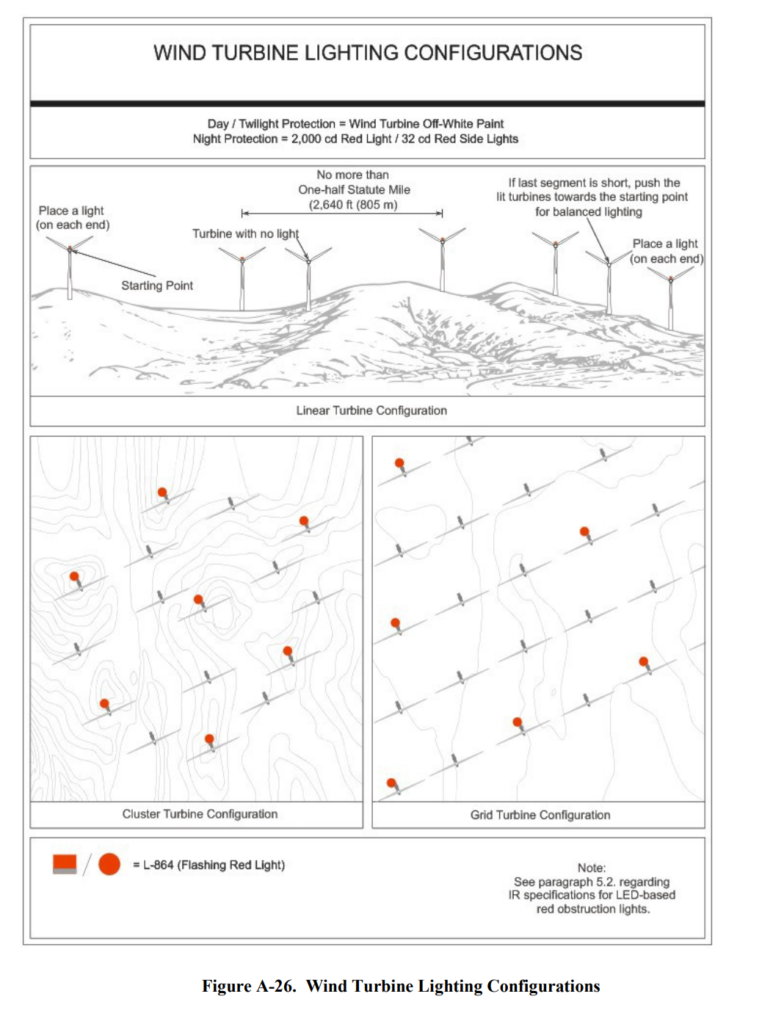
1. Linear. Wind turbine farms in a direct, consecutive configuration, often located along a ridgeline, the face of a mountain, or along borders of a mesa or field. The line may be ragged in shape or be periodically broken, and may vary in size from just a few turbines to many turbines forming a line that is several miles long.
2. Cluster. Wind turbine farms arranged in circular configuration. A cluster is typically characterized by having a pronounced perimeter, with various turbines placed inside the circle at various, erratic distances throughout the center of the circle.
3. Grid. Wind turbine farms arranged in a geographical shape, such as a square or a rectangle, in which the turbines are placed a consistent distance from each other in rows, giving the appearance that they are part of a square pattern.11/16/2020 AC 70/7460-1M 51
13.4 Marking Standards.
13.4.1 Wind turbines should be painted white or light grey, as these colors have been shown to be the most effective method for providing daytime conspicuity (see Figure A-26). Wind turbine manufacturers typically use a European color-matching system that is referred to as the RAL Color Standard. The RAL system uses a four-digit code to identify a specific color of paint, for example, an RAL 9xxx code would represent a color in the white/black range. The preferred white paint color is pure white, RAL 9010, or an equivalent, however most wind turbines currently produced are painted light grey, RAL 7035, which is the darkest acceptable off-white paint allowed. Any shade of white between these two RAL specifications is strongly recommended (see Table 13-1). Table 13-1. Wind Turbine Paint Standard Colors Color RAL Number Pure White (preferred color) 9010 Light Grey (Darkest Acceptable) 7035
13.4.2 In geographic areas that experience lengthy periods of snow cover (i.e., Alaska), and where it is deemed necessary, the mast of the turbine may be painted alternating bands of aviation orange and white to provide additional contrast against the snow. The nacelle and blades of the turbine must remain solid white or light grey (see Figure A-27).
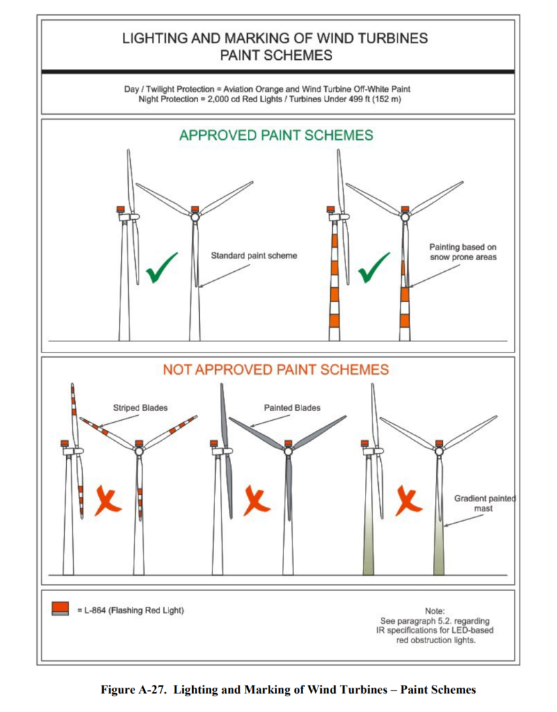
13.4.3 Blades or blade tips must not be painted or manufactured in colors to camouflage wind turbines with the surrounding terrain.
13.4.4 For turbines that are constructed with lattice-type masts, the mast structure must be painted with alternating bands of aviation orange and white paint, in accordance with Chapter 3. The turbine’s nacelle and blades must remain solid white or light grey.
13.5 Lighting Standards.
13.5.1 Studies have shown that red lights provide the most conspicuity to pilots, therefore during nighttime hours and periods of reduced visibilities, wind turbine obstruction lighting should consist of FAA L-864 aviation red flashing, strobe, or pulsed obstruction lights. Any array of flashing, strobe, or pulsed obstruction lighting should be synchronized to flash simultaneously (within ±1/20 second (0.05 second) of each other). Light fixtures should be placed as high as11/16/2020 AC 70/7460-1M 52 possible on the turbine nacelle so they are visible by a pilot approaching from any direction (see Figure A-28). Should any lighting fixture or the lighting system synchronization fail, a lighting outage report should be prepared in accordance with chapter 2, paragraph 2.4. Daytime lighting of wind turbines is not required. See paragraph 14.4 for daytime marking requirements.
13.5.2 In most cases, not all wind turbine units within a wind turbine farm need to be lighted. Obstruction lights should be placed along the perimeter of the wind turbine farm so that there are no unlit separations or gaps more than 1/2 SM (0.80 km). Wind turbines within a grid or cluster should not have an unlighted separation or gap of more than 1 SM (1.61 km) across the interior of a grid or cluster of turbines (see Figure A-25). 1. Linear Turbine Configurations: Lights should be placed on the turbine positioned at each end of a line or string of turbines. Lights should also be placed along the line of turbines so that there is no more than a 1/2 SM (804.67 m) gap between the lighted turbines. In the event the gap between lights on the last segment of turbines is significantly short, it may be appropriate to move the lights on the turbine string back toward the starting point to present a well-balanced string of lights. High concentrations of lights should be avoided. 2. Cluster Turbine Configurations. A turbine should be selected as a starting point along the outer perimeter of the cluster. The turbine should be lighted, and a light should be placed on the next turbine along the perimeter of the cluster (clockwise or counterclockwise) so that no more than a 1/2 SM (804.67 m) gap exists. This pattern should be continued around the perimeter of the cluster until the starting point is reached. In the event that the gap between the lights on the last segment of turbines is significantly short, it may be appropriate to move the lights along the perimeter of the cluster back toward the starting point to present a well-balanced perimeter of lights. If the distance across the cluster is greater than 1 SM (1.61 km), additional lights should be placed on other turbines throughout the center of the cluster so that there are no unlighted gaps across the cluster. For example, if the distance across a wind turbine farm is 1.8 SM (2.90 km), a light should be placed on a turbine at approximately every 0.9 SM (1.45 km). 3. Grid Turbine Configurations. Turbines on the corners of the farm should be lit, and then use the same concept for selecting which turbines should be lit as outlined in paragraph 13.5.3.
13.5.3 Special Considerations. Occasionally, some wind turbines may be located apart from the main group of turbines. If one or two wind turbines protrude from the general limits of the turbine farm, these turbines should be lighted in addition to those identified in the main group. Additional lighting may be necessary on wind turbines located on the interior of a cluster or grid configuration whose height is 100 feet (30.48 m) or higher than the other wind turbines located within the farm.11/16/2020 AC 70/7460-1M 53
13.6 Wind Turbines Above 499 Feet (152.10 m).
13.6.1 For wind turbines with a rotor tip height, while at top dead center, greater than 499 feet(152.10 m) AGL, but less than 699 feet (213.06 m) AGL, the turbines should be lighted in accordance with paragraph 13.5. In addition to these requirements, the top of the turbine’s nacelle should be equipped with a second L-864 flashing red light (see Figure A-28).
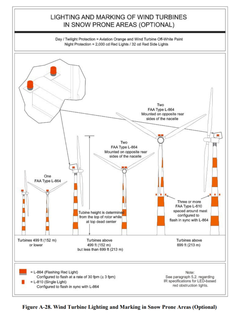
13.6.2 The two obstruction lights should be arranged horizontally, positioned on opposite sides of the nacelle, visible to a pilot approaching from any direction, and flash simultaneously. Using this lighting configuration ensures the conspicuity of turbines in this size category.
13.6.3 In the event one of the two obstruction lights fails, no light failure notification is required; however, the light should be restored to service as soon as possible.
13.6.4 All turbines within this size category should be illuminated, regardless of their location within a wind turbine farm, and should be configured to flash simultaneously with the other turbines in the same farm. This requirement ensures the pilots operating at low altitudes above 500 feet AGL have sufficient warning that a wind turbine obstruction may be within their flight path.
13.7 Wind Turbines at or Above 699 Feet (213.36 m).
13.7.1 For wind turbines with a rotor tip height, while at top dead center, at or above 699 feet (213.06 m) AGL, additional lighting is required. All wind turbines of this size, regardless of number or configuration should be lighted.
13.7.2 In addition to the lighting identified in paragraphs 13.5 and 13.6, an additional level of lights is required at a point midway between the top of the nacelle and ground level. The location of the additional lights may be adjusted as necessary to allow mounting at a seam within the turbine’s mast.
13.7.3 The additional level of lights should consist of a minimum of three L-810 F flashing red lights configured to flash in unison with the two L-864 red flashing lights located at the top of the nacelle at a rate of 30 fpm (± 3 fpm). The L-810 F lights should be spaced at equal distances around the mast to ensure a pilot approaching from any direction has an unobstructed view of at least two of the lights (see Figure A-28).
13.7.4 For wind turbine structures with a mast diameter greater than 20 feet (6.10 m), four L- 810 red lights should be used.
13.7.5 All turbines within this size category should be illuminated, regardless of their location within a turbine farm, and should be configured to flash simultaneously with the other turbines in the same farm. This requirement ensures the pilots operating at low altitudes above 500 feet AGL have sufficient warning that a wind turbine obstruction may be within their flight path.11/16/2020 AC 70/7460-1M.
Summary
The integration of wind farms into our energy ecosystem presents a unique blend of challenges and opportunities. While they symbolize a step towards a cleaner, sustainable future, it’s essential to ensure they don’t compromise aerial safety. Through careful planning, strategic positioning, and understanding the unique nature of each wind farm, we can ensure that the skies remain safe for pilots and aircraft. As the wind continues to power our homes and businesses, let’s also ensure it fosters safety and harmony in our skies.